![]()
|
|
|
|
100 Hp, Mobile Drilling Rig Specification and Main Parameters Ø Electrical Driven Drill Rig ZJ40/2250DB Ø Rated Drilling Depth of 3500 m with 127mm (5”)DP & 4000 m with 114mm (4-1/2”)DP Ø Rated Maximum Static Hook Load: 2250KN Ø Cantilever Type mast 43m High Ø Vertical Self Raising / Lowering Type with Hydraulic Winch Ø Capacity of Set Back Board: 4000m (4-1/2”DP), 4 stands of 10” DC & 6 stands of 8” DC Ø Substructure Floor Height of 7.5m with a Clearance of 6.2m Ø Ground Level Completely Assembled Slingshot Type Drawworks Ø 1000Hp Rated Input Auxiliary Generators 800Kw, 3 Phase, 60 Hz, 600v, 0.8PF, 1000 KVA Ø Rotary Table ZP275, 27 1/2” Opening, Independent and Single AC Motor Drive, Maximum Rated Static Load: 3150KN Ø 1360HP Single shaft & one AC Drive Motor Ø Maximum Fast Line Pull of 280KN Ø Solids Control System Total Tank Volume: 135 m3 Ø Allowable Wind Velocity of 180km/hr Ø Lines Strung: 5×6 Ø Size of Drill Line: 1 1/4” Ø Main Engines: 2 × CAT 3512 DITA Ø Mud Pumps: 2 × 1300HP Ø Crown Block: TC225, 2250KN Ø Traveling Block: YC225, 2250KN Ø Hook: DG225, 2250KN Ø Swivel: SL250, 2500KN Ø 3 Elliptic Motion Shale Shakers Ø 1 Degasser Ø 1 De-sander Ø 1 Desilter Ø 1 centrifuge Ø 1 Mud shearing pump
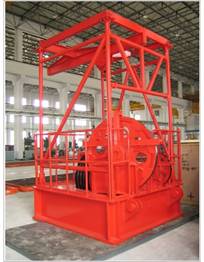
Corollary Equipment Description The Mast Ø JJ225/43K is ground assembled with a special cantilever type assembling rack, and can be assembled at low elevation, vertically raised by two hydraulic winches mounted in the substructure, conformance to API 4F, AISI spec for structural steel building and AWS D1.1-2002 structural welding code, suitable for top drive installation. Ø “K “ Frame assembly Ø Racking Platform Ø Ladder Assembly Ø Counterbalanced Weight of Power Tongs Ø Adjustable Casing Stabbing Board Ø Stand Pipe Operation Board Ø Bracket of Wire Line Stabilizer Ø Wind Walls Ø Standpipe Clamps Ø Climbing Assistor Ø Auxiliary Sheaves Ø Tong Sheaves Ø 2 × Air Winch of 0.5t Capacity Ø A Set of Connection Pins Ø Maximum Static Hook Load: 2250kN with 10 lines strung Ø Effective Height: 43 m Ø Available Heights of Racking Platform: 24.5, 25.5, 26.5 (m) Ø Capacity of Racking Platform: 4500 m of 5” Drilling Pipe, 4 Strands of 10” Drill Collars & 6 Strands of 8” Drill Collars Ø Rated Wind Load: o No Setback and Full of Hook Load: 36 m/s (70 knots) o No Setback and No Hook Load: 47.8 m/s (93 knots, 172,8 km/hr) o Raising and Lowering: = 8.3 m/s (16 knots)
The Substructure Ø DZ225/7.5 SUBSTRUCTURE, to API 4F Ø Bottom Layer Ø Top Layer Ø Drillers Floor Ø Middle Layer Assembly Ø Pipe Setback (spreader) Ø Rotary Table Frame (spreader) Ø Driller and Tool House brackets Ø Floor Plates Ø Stairs with guards Ø V-door Ø Combination of Stair, Ramp, & Guide Track Beneath the Top Floor Catwalk
Ø 7.5 m High, 6.2 m Clearance Ø 8×11.2 (m2) Drilling Floor Ø 2250KN Rated Maximum Load on the Rotary Table Spreader
Ø
1800KN Rated
Maximum Setback Load Applied in Combination with the Rated Rotary Load, with
Setback Capacity of 4000 m with 4 1/2” Drill Pipe Drawworks Ø Maximum Input Power of 1100kw (1360Hp), Single Shaft Ø Main Brake is a Hydraulic Disc Brake with Crown Block Protector Ø Grooved Drum Ø The Drum Shaft is Made of Alloy Steel Ø The safety Coefficient Meets API Spec 4F Ø The ventilated and small air chamber clutches are applied for high and low speed shafting and feature high sensitivity, lower air-consumption, greater torque and longer life Ø The Emergency Accident Pins are prepared for Low Speed Clutch. Ø The Upper (Crown saver) and Lower Traveling Block Limit (floor saver) are Automatically Controlled
AUTO-DRILLING SYSTEM Ø Using the VFD control & AC motor drive to realize the very accurate WOB, the WOB tolerance can be kept within ±0.5ton. Also, in an emergency, the driller can use the auto-drilling system to trip out of the hole. Crown Block Protector Ø Maximum Fast Line Pull: 280 KN Ø Diameter of Main Drum (grooved): 640×1302 mm Ø Diameter of Drill Line: 1-1/4” Ø Range of Drilling Penetration:2500-4000 m Ø Individual and Totally Enclosed Case Structure Ø Movable as an Integrated Unit Ø Complete with two sets of pump groups that are stand-by each other; In this system there are two independent sub-circulation oil routes respectively mounted for the service calipers and emergency calipers. In the independent service caliper sub-oil-circulation system there are also two independent oil paths for providing oil for the two groups of service calipers, respectively mounted on two ends of the main drum, decreasing the possibility of failure, With the independent sub-circulation oil route specially mounted for emergency calipers, the holding brake, the crown protector and the emergency braking system can all be utilized. Once the hydraulic pressure is lost, the brake is automatically applied with the emergency calipers, and if the pump groups fail, hydraulic oil can be fed with the accumulator in system into calipers to apply the brakes 4-6 times.
TC-225 CROWN BLOCK Ø Meets Requirements of API 8A, 4F Ø Maximum Rated Static Hook Load: 2250KN Ø 5 × Sheave (OD of 1120 mm) Grooved for 1-1/4” Drill Line with Gin-Pole Installed Ø 1 × Sheave for Fast Line Ø 1 × 1ton Crane Ø 2 × Auxiliary Sheave Ø Dimensions: 2935× 1320× 2300 (mm) Ø Weight: 7497KG
YC-225 TRAVELING BLOCK
Ø Meets Requirements of API 8A Ø Maximum Rated Static Hook Load of 2250KN Ø 5 × Sheave (OD of 1120 mm) for 1-1/4” drilling line Ø Dimensions: 3075×1600×800 (mm) Ø Weight: 8135 kg DG-225 HOOK
Ø Meets Requirement of API 8A Ø Maximum Rated Static Hook Load of 2250KN Ø Opening Size: 220mm Ø Working Range of the Spring: 200mm Ø Dimensions: 2950×890×883 mm Ø Weight: 3496KG
SL250 Swivel
Ø Meets Requirements of API 8A Ø Static Load of Maximum 2500 KN Ø Revolution of 300 rpm Ø Service Pressure of 34.3 MPa Ø Internal Diameter of Swivel Stem: 75mm(3”) Ø Connection Threads: 7-5/8” REG LH to Stem 6-5/8” REG LH to Kelly Pipe Ø Dimensions: 3015×1000×960 (mm) Ø Mass: 3461kg ZP-275 ROTARY TABLE
Ø Meets Requirements of API 7K Ø 27-1/2” Opening Ø Maximum Rated Static Load of 3550KN Ø Maximum Working Torque of 29362NM Ø Maximum Revolution Speed of 250rpm Ø Gear Ratio: 3.67 Ø Distance from Table Axis to Center of Inner Row of Sprocket Teeth: 1353 mm Ø Weight: 7548kg Ø Dimensions: 2390×1670×685(mm) Ø Lifting Sling Assembly Ø Independent Drive Unit for Rotary Table. The Rotary Table is Driven by a Single AC motor Ø One Speed Chain Transmission with Chain Case Ø One Inertia Brake Bushings (Option)
Ø 5 1/4” Kelly Roller Bushing Ø 2-3/8” - 8-5/8” Insert Bowl Ø 9-5/8” - 10-3/4” Insert Bowl Ø 11-3/4” - 13-3/8” Insert Bowl Ø 20” Bushing
Mud Pumps
Ø 2 × 1300HP Pumps conforming to API 7K Ø Triplex Action Pumps, 1300HP(1176KW) Ø Maximum Working Pressure of 35MPa Ø Piston Diameters Available: 150 mm, 160 mm, 170 mm, 180 mm Ø Maximum Discharge of 46.6L/Sec
Ø
Stroke Speed:
120 spm 1300HP UNITIZATION UNIT
Ø Driven by AC Motor with Narrow “V” Belts Ø 1 ea Unit Master Skid with Adjustable Threaded Bolts Used for Adjusting Belt Tension Ø 1 ea Electrical Motor Drive Spraying Pump Ø 1 ea Discharge Strainer Cross with Discharge Flange Connection Ø 4” x 35 MPa Top Pulsation Dampener Connection and End Strainer Connection Ø 1 ea Discharge Pulsation Dampener, 75L (20 gal) capacity, 35MPa with 4”and 35 MPa Connection Ø 1 ea Relief Valve with Discharge to Active Tank and Matched with Pressure Rating Ø 1 ea Jib Crane with Trolley Installed and Sized to Handle Fluid End Parts and Pulsation Dampeners Ø One set of Quick Change Valves Ø Discharge Pressure Gauge and Nitrogen Filling Pressure Gauge Ø Charge Pumps with Motors (60Hz) Ø Each rig should be provided with one Mud Charge unit, which consists of two (2) charge pumps (ea 55KW) with AC motors (60Hz, speed matched with the charge pump), suction and charge pipeline, control valves for two (2) mud pumps and a skid. Ø The electrical charging pumps are connected in parallel with the two mixing pumps in solids control system. DH250 Elevator Link
Ø Meets Requirements of API 8A Ø Rated Capacity: 250 KN
TJC-50A Hoist Winches on rig Floor Ø Rated Pull of 50 KN
Air Winch
Ø Working Pressure: 0.7 MPa Ø Maximum Drawing Force: 50 KN Ø Maximum Lifting Velocity: 35 m/min Ø Air Motor: Rated 15 KW (60Hz), Piston Stroke of 76 mm, with Five Cylinders Ø Drum: D of 220 mm, W of 435 mm, with D of Rim of 485 mm
Ø
Wire Rope: D of 15.875mm,
Length of 70 m Ø Mass and Dimension: 418 kg, 1254 (L)×900 (W)×989 (H) (mm) Ø JZG25 Dead Line Anchor (332kg) Ø Air winch at racking platform level to aid racking the drill collars (Hoist winches in racking platform rated pull of 1000 lb) Ø Escape line from racking platform to ground with all accessories Ø Wire line stabilizer unit
Drilling Line
Ø 1-1/4” Diameter Ø 6X19+IWR EIPS Ø 1000 m Long Ø As per API 9A
Electric Motors & Control Devices
Ø Equivalent to GE in dimensions, size and performance, one 400KW motor for the rotary table, one 1100KW AC motor for the drawworks, one 1000KW AC motor for the mud pump, and another small AC motor(37KW) for the auto-drilling system Ø 4 × MCC Switchgear Ø 1 set of copper bus bar and receptacles/ plugs Ø 1 × Protection Devices Ø 2 × Air Conditioners Ø 1 × Resistor box using for dynamic braking of auto-drilling motor Ø The MCC control system is divided into several sub-units per the power users and control ways, with control cubicle of drawer configuration that is changeable each other if they belong to same family. These cubicles are applied to operate, start and protect the AC motors and lighting lamps Ø A number of power supply loops can be set in conformity with customer’s requirements Ø Driller’s electric control panel Constructed by stainless steel, positive pressure and explosion proof Ø PLC slave station Ø Indication lamps for power restriction, working status of rectifiers and AC motor blowers Ø Indicators for power restriction percentage, torque of rotary table Ø Operation switches for designating mud pumps, draw-works and rotary table Ø Rotary table hand-wheels for torque restriction and speed adjustment Ø Alarm Buttons for emergency shut down, silencer and lighting test
Electric Distribution System
Ø Power contribution system over well site ( solid control, water supply, fuel supply and drill floor area) AC motors rated = 30 KW are started in VFD room and only the explosion-proof starting buttons are left beside motors; AC motors rated = 30KW are controlled locally and power supplied by VFD room Ø Cables connected to motors, explosion proof sub-switchgears, normal switchgears
Ø Start/stop buttons, receptacles/ plugs and Lighting system (60 Hz) including fixtures, receptacles/plugs, cables, fittings and the fluorescent and metal halide type lamps using for rig per relevant standards
Ø Air supply system The system supplies compressed air to two generator sets, one auxiliary generator and the air winch installed on the drilling platform
Ø The system includes two (2) auto-control electric drive rotary screw compressors. Pressure range is from 0.7 MPa to 1.2 MPa with capacity of 4.6-6.1 m3/min each (> 100 ft3/min), one refrigerant type dryer, coarse / fine filters, and pipeline net, installed in the rooms; The compressed air container is 2.5 m3
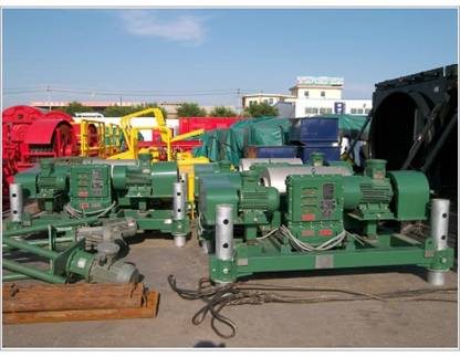
Solid Control System
Ø Available effective volume of 135m3 Ø This system, as an integral unitized package, mainly consists of 3 mud tanks (each 3W× 12.5L× 3.4H m), and 4-stage treatment device. Ø The 1# mud tank is partitioned into three compartments and equipped with three Elliptic motion shale shakers, centrifugal vacuum degasser, two agitators and mud guns, one metering pump with one sand pump on the right side and works as a solid control tank
Ø The 2# tank is equipped with a desander and desilter cleaner (a combination of hydro-cyclones and screens) with a sand pump on the left. It is able to remove > 40:140µm and > 20:43µm particles respectively)
Ø The 3# mud tank is fitted with 1 centrifuge of >2µm particle removable and two mixing pumps ea 55 KW, one 45 KW shear pump , two hydro-cyclone type mixing hoppers, drugs feeding devices and mud guns etc, forming the mud preparation section by means of the hydro-cyclone and jet type mixers, the materials such as polymers, clays, bologna stone powder (Blanc fix) etc can be mixed quite well to be the qualified drilling fluid
Ø The 2# and 3#mud tanks are equipped with three agitators respectively; the mixing pumps on the 3# mud tank can suck mud simultaneously or individually out of the 2# and 3# tanks by the mixing hopper. Treated mud can be sent back to any one of the tanks
Ø The electrical charging pumps are connected in parallel with the two mixing pumps. Opening the 10” mud valve as required during drilling course, they can also simultaneously or individually suck mud out of the 2# and 3# mud tanks
Ø Because the solid control system is unitized and the tyre unions, rubber unions and hoses are widely adopted, the system is easy for installation
Ø 3× mud tanks with skid, rimmed and crimped walls, gunning and watering line full length arranged, hummer seal pit union type connection, side wall dumping gates, all pipeline, valve, lever operated suction valve, flow-line and butterfly valve for connection/disconnection between tanks, covered top of removable walkways, and one set of ladders and stairs.
Ø 3×GW-1 Elliptic Motion Shale Shakers Ø 1 set of GW-2 De-Sand/de-Silt Cleaner Ø 1 ZCQ-1 Vacuum Degasser, Ø 1 LW450-842n Centrifuge Ø Sand Pumps Ø Agitators (NJ-15 and NJ-11), Ø Charge Pumps for Sand Pump Table Ø Mixing Pump Ø Shear Pump Ø Metering Pump Ø Jet Type Mixing Hopper, Ø Rotary Mud Gun Ø Drug Feeding Device
High Pressure Mud System
Ø Single standpipes, 101.6 mm (4”) ID×35 Mpa Two 4” ID standpipes with gooseneck, with “H” shape standpipe manifold.
ZJGH-35S Drilling Fluid Manifold (for double Standpipes)
Ø Nominal I.D. of through hole: 4” Ø Practical I.D. of through hole: 94—109 mm Working pressure: 35 Mpa Applicable temperature: -29?-121 Ø Applicable medium: Fresh water, drilling fluid, crude oil, cracking fluid connection manner: union Drive manner of gate valve: manual Ø Weight: 6000kg Ø Rotary Hoses Ø 3-1/2”ID×60’ long, 5000 Psi WP
Fuel Supply System
Ø 1 fuel tank of 50m³,input and output indicators Ø 2×centrifugal pump Ø Level indicator and manifold Drilling Instruments Ø SHENKAI produced Ø Parameters being monitored and warned: o WOB o RPM of RT o Torque of RT o Torque of hydraulic tong o SPM of MP o Pump Pressure o Standpipe Pressure o Return Volume of mud to well head o Depth of Well o (Real-time) Volumes of mud tank and trip tank etc
Ø Technical requirements applicable: o AC supply: 220V±20%, 60Hz±10% o Hook load: 0—4200KN with the dial (scale or graduated disk) calibrated for 10/20 lines strung o Revolution speed of RT: 1-300 rpm o Torque of RT: 1-100 KNM o Torque of hydraulic tong: 1-200 KNM o SPM of MP (1#,2#,3#): 0—200 SPM o Pump Pressure: 0—40 MPa o Return Volume of mud to well head o 0—100% o Level of mud tank 0.25—5 m o Real time Depth of well: 0—9999 m. Ø Accuracy of instruments: o Displaying: ±2.5% o Recording: ±10%.
SENSORS Ø 2× pump stroke Ø 1× revolution speed of rotary table Ø 1× encoder of penetration Ø 1× pressure conversion unit Ø 1× weight conversion package Ø 1× torque of rotary table Ø 1× standpipe pressure Ø 1× return rate of mud from wellhead Ø 1× torque of tong Ø 5× ultrasonic sensor DAQ (date acquisition unit)
Ø Including calibration programs and units Ø WOB Ø Torque of RT Ø Pressures of standpipes Ø Torque of tongs Ø Stokes of pumps Ø Revolution speed of RT Ø Return rate of mud from well head Ø LCD of E-Drill Watch Accessories Ø Computer workstation Ø Printer Ø UPS cable Ø Hydraulic pipes and connections Ø Assembly accessories Ø Tools Water Supply System & Boiler
Ø Industrial water supply system Ø 1 set of water tanks with total volume of 80m³, two centrifugal pumps and Pipeline YM1011 Hydraulic Cathead
Ø Complete with hydraulic station Ø Make up pull of 100 KN Ø Break out pull of 130 KN Ø The drawing pull can be adjusted as required with correct choice of operation model Ø Rated WP = 16 MPa Ø Flow rate = 120 L/min Ø Drawing traveling distance = 1400, 1620, 1650, 1920 mm
Cathead-cylinder and cathead
Ø 34SM-B20H-T manual-direction-valve with control box connected to hydraulic station Ø YK-100 pressure gauge Ø Connection assembly Hydraulic Tong
Ø ZQ-100, 10 KNM, with hydraulic station Ø Applicable pipe OD (in): 3-1/2”---8” Ø Max torque (NM): 100×103 Ø The speed of tong head (Hi) (rpm): 40 Ø The speed of tong head (Lo) (rpm): 2.73 Ø Hydraulic system pressure rating (MPa): o 16.6 Hydraulic system flow rating (L/min) o 114 Forward extent of tong head (m) o 1.5 Normal pressure of pneumatic system (MPa) o 0.5-1 Overall dimensions (mm): 1700×1000×1400 o Weight (Kg): 2400 TQ340-35 Casing tong
Ø Applicable pipe OD (in): 4”---13 3/8” Ø Max torque highgear:6.0-7.5KN.m Ø Max torque low gear: 60-86KN.m Ø The speed of tong head (Hi) (rpm) Ø 60-86 The speed of tong head (Mid) (rpm) Ø 21-30 The speed of tong head (Lo) (rpm): 2.6-5.3 Ø Weight 780kg Ø Manual Tong B Applicable pipe OD (in): 4”---8 1/2”
Ø
Rated torque
88.2KN.M Misc. Ø Hydraulic scissor Ø Flotation type caliper of mouse-hole Ø Fuel, air and water pipeline system and cable trays
|
Send mail to
jack@dwracinggraphics.com with
questions or comments about this web site.
|